January 7, 2023
Note: The simulator code is heavily inspired by two posts on itsembedded.com {1, 2}.
Here's the (system)verilog file:
test.sv
module test(input clk, input reset);
  // constants
  parameter THRESHOLD = 10 - 1;

  // variables
  enum bit[0:0] {OFF, ON} led_status = OFF;
  integer unsigned counter = 0;

  always @(posedge clk or posedge reset) begin
    $display ("LED status is %d counter is %d", led_status, counter);
    if (reset == 1) begin
      led_status <= OFF;
      counter <= 0;
    end else begin
      if (counter == THRESHOLD) begin
        led_status <= led_status.next();
        counter <= 0;
      end else begin
        counter <= counter + 1;
      end
    end
  end
endmodule
And our test bench c++ file:
sim_test.cpp
#include
#include
#include
#include
#include "Vtest.h"

// Change MAX_SIM_TIME to the number of clock cycles you want. If set to 100,
// it means the clock will be 50 times on 1 and 50 times on 0.
#define MAX_SIM_TIME 1000
vluint64_t sim_time = 0;

int main(int argc, char** argv, char** env) {
    // dut = DEVICE UNDER TEST (points to the verilog module).
    Vtest *dut = new Vtest;

    Verilated::traceEverOn(true);
    // Instantiate a tracer so that we can visualise it later.
    VerilatedVcdC *m_trace = new VerilatedVcdC;
    // 5 represents the depth of the dut.
    dut->trace(m_trace, 5);
    m_trace->open("waveform.vcd");

    while (sim_time < MAX_SIM_TIME) {
        dut->reset = 0;
        if (sim_time > 25 && sim_time < 100) {
          // for a few cycles, pretend the reset button is on.
          dut->reset = 1;
        }
        // switch the clock from 0 to 1.
        dut->clk ^= 1;
        // evaluates the design.
        dut->eval();
        // stores the trace.
        m_trace->dump(sim_time);
        sim_time++;
    }
    m_trace->close();
    delete dut;
    exit(EXIT_SUCCESS);
}
To compile the traces run:
verilator --cc --trace --exe --build -j 0 -Wall sim_test.cpp test.sv && obj_dir/Vtest
and to run the waves file:
gtkwave waveform.vcd
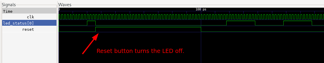
The wave looks like this, and proves the reset button behaviour: